© 2017 Cisco and/or its affiliates. All rights reserved. This document is Cisco Public. Page 1 of 6
Packet Tracer – Explore Network Functionality Using PDUs
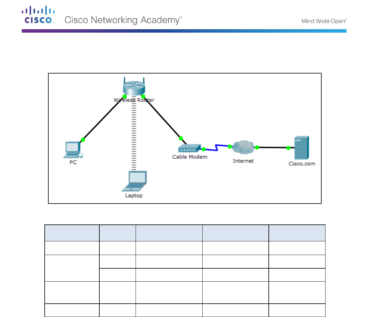
Topology
Addressing Table
Device
Interface
IP Address
Subnet Mask
Default Gateway
PC
Ethernet0
DHCP
192.168.0.1
Wireless Router
LAN
192.168.0.1
255.255.255.0
Internet
DHCP
Cisco.com
Server
Ethernet0
208.67.220.220
255.255.255.0
Laptop
Wireless0
DHCP
Objectives
Part 1: Create a Simple PDU in Simulation Mode
Part 2: View Contents of PDUs
Part 3: Create a Complex PDU in Simulation Mode
Background / Scenario
In this activity, you will open the saved Packet Tracer activity that was completed in Chapter 2, and use the
Simulation mode to create PDUs to explore network functionality.
Packet Tracer – Explore Network Functionality Using PDUs
© 2017 Cisco and/or its affiliates. All rights reserved. This document is Cisco Public. Page 2 of 6
Part 1: Create a Simple PDU in Simulation Mode
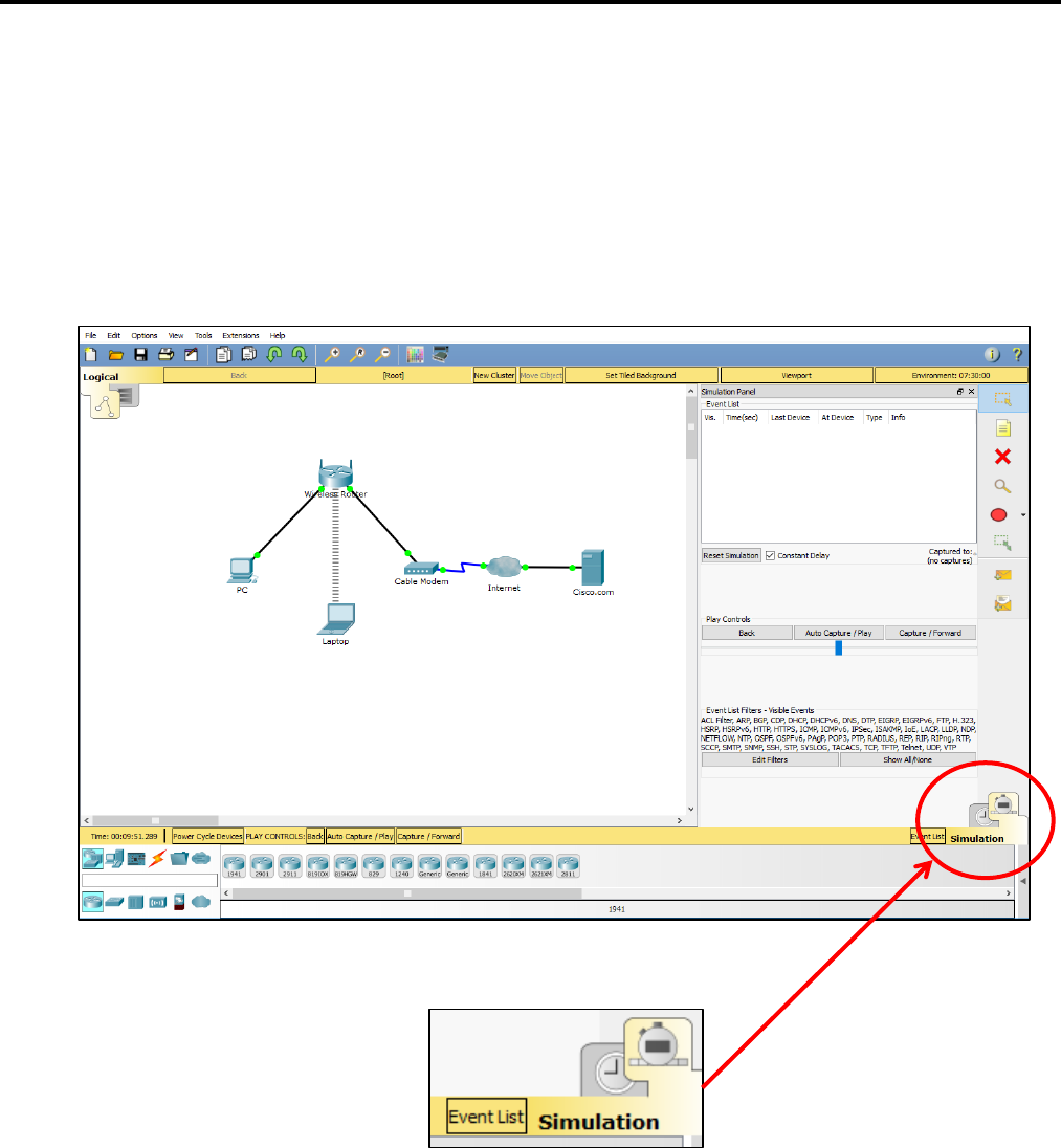
Step 1: Open the .pka activity
a. Navigate to the .pka activity that was completed in Chapter 2.
Navigate to the directory that contains the Packet Tracer Activity that was completed in Chapter 2. Open
the activity and click the Simulation mode icon in the bottom-right corner of the Packet Tracer window to
open the Simulation panel.
Step 2: Create a simple PDU.
a. Create a simple PDU that sends a ping from the PC to the laptop
Click the Add Simple PDU icon (looks like a closed envelope) in the right pane of the Packet Tracer
window. The curser will change to an envelope with a plus sign. Click the PC first so it will become
the source of the ping and then click the Laptop so that it will become the destination.
Packet Tracer – Explore Network Functionality Using PDUs
© 2017 Cisco and/or its affiliates. All rights reserved. This document is Cisco Public. Page 3 of 6
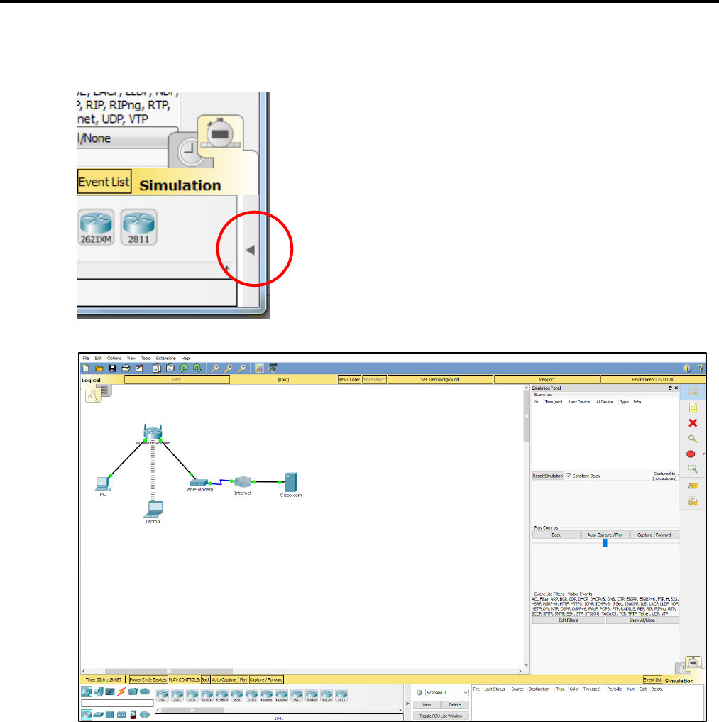
Expand the Event Simulation pane by clicking the gray arrow at the bottom right of the Packet
Tracer Window.
b. Observe traffic moving through the network.
Click the Capture/Forward button and observe the traffic move through the network each time the
button is clicked. Notice also that each time the Capture/Forward button is clicked, sent packets are
displayed in the Event List window. Continue clicking the Capture/Forward button until the return
ICMP packet makes it back to the PC.
Packet Tracer – Explore Network Functionality Using PDUs
© 2017 Cisco and/or its affiliates. All rights reserved. This document is Cisco Public. Page 4 of 6
Part 2: View Contents of PDUs
Step 1: Use event list to see PDU information
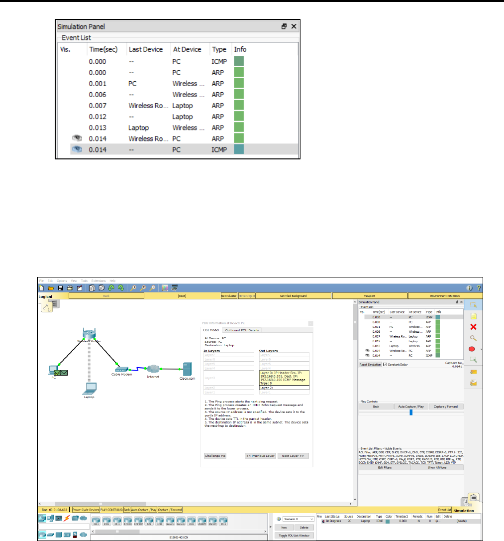
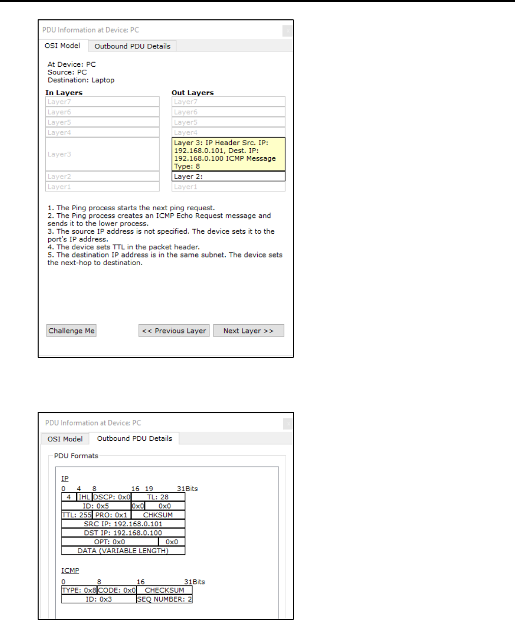
a. View the information of the first ICMP PDU packet from the PC.
In the Event List window, click the green square under the Info column for the first ICMP PDU at the top
of the list. This will open the PDU Information at Device: PC window.
Observe the information in the OSI Model tab. Notice that this is an outbound Layer 3 PDU and the
source and destination IPv4 address is shown.
Packet Tracer – Explore Network Functionality Using PDUs
© 2017 Cisco and/or its affiliates. All rights reserved. This document is Cisco Public. Page 5 of 6
Next, click the Outbound PDU Details tab. Notice that this tab shows details of the protocol headers.
b. Explore the contents of other PDUs listed in the Simulation Panel and review the information that is
available in each.

Packet Tracer – Explore Network Functionality Using PDUs
© 2017 Cisco and/or its affiliates. All rights reserved. This document is Cisco Public. Page 6 of 6
Step 2: Delete the simple PDU
c. Delete the simple PDU using the Event Simulation pane.
Click the Delete button in the Event Simulation pane at the bottom of the Packet Tracer window. Notice
that this removes the simple PDU and clears out all PDUs from the Simulation Panel Event List.
Part 3: Create a Complex PDU in Simulation Mode
Step 1: Create a complex PDU
a. Add a complex PDU to send pings from the PC to the laptop.
Click the Add Complex PDU icon, the one that looks like an open envelope, in the right pane of the
Packet Tracer window. The curser will change to an envelope with a plus sign. Click the PC first so it
will be the source device of the pings and then click the Laptop so that it will be the destination.
The Create Complex PDU window will display.
b. Configure complex PDU settings to send the pings every 5 seconds.
In the Create Complex PDU window, there are many settings which can be customized. To send a
ping every 5 seconds from the PC to the laptop, the Destination IP Address field must have the IPv4
address of the laptop, 192.168.0.100. The Source IP Address field should be the IP address of the
PC, 192.168.0.101. At the bottom in the Simulation Settings section click Periodic and set the
Interval to 5 seconds.
c. Observe traffic moving through the network.
Click the Auto Capture / Play button and watch the traffic move through the network and notice the
PDUs populating the Simulation Panel Event List. Because we set the complex PDU to an Interval of
5 seconds, a new PDU will be created every 5 seconds. Click the Auto Capture / Play button again
to stop the simulation.
To delete the complex PDU, click the Delete button in the Event Simulation pane at the bottom of
the Packet Tracer window.
