© 2013 - 2021 Cisco and/or its affiliates. All rights reserved. Cisco Public Page 1 of 7 www.netacad.com
Packet Tracer - Configure VLANs and Trunking - Physical Mode
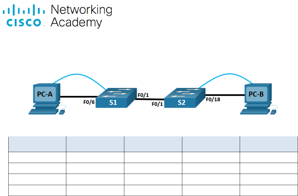
Topology
Addressing Table
Device
Interface
IP Address
Subnet Mask
Default Gateway
S1
VLAN 1
192.168.1.11
255.255.255.0
N/A
S2
VLAN 1
192.168.1.12
255.255.255.0
N/A
PC-A
NIC
192.168.10.3
255.255.255.0
192.168.10.1
PC-B
NIC
192.168.10.4
255.255.255.0
192.168.10.1
Blank Line - no additional information
Objectives
Part 1: Build the Network and Configure Basic Device Settings
Part 2: Create VLANs and Assign Switch Ports
Part 3: Maintain VLAN Port Assignments and the VLAN Database
Part 4: Configure an 802.1Q Trunk Between the Switches
Background / Scenario
Modern switches use virtual local-area networks (VLANs) to improve network performance by separating
large Layer 2 broadcast domains into smaller ones. VLANs can also be used as a security measure by
controlling which hosts can communicate. In general, VLANs make it easier to design a network to support
the goals of an organization.
VLAN trunks are used to span VLANs across multiple devices. Trunks allow the traffic from multiple VLANS to
travel over a single link, while keeping the VLAN identification and segmentation intact.
In this Packet Tracer Physical Mode (PTPM) activity, you will create VLANs on both switches in the topology,
assign VLANs to switch access ports, and verify that VLANs are working as expected. You will then create a
VLAN trunk between the two switches to allow hosts in the same VLAN to communicate through the trunk,
regardless of which switch to which the host is attached.
Instructions
Part 1: Build the Network and Configure Basic Device Settings
In Part 1, you will set up the network topology and configure basic settings on the PC hosts and switches.

Packet Tracer - Configure VLANs and Trunking - Physical Mode
© 2013 - 2021 Cisco and/or its affiliates. All rights reserved. Cisco Public Page 2 of 7 www.netacad.com
Step 1: Build the network as shown in the topology.
Attach the devices as shown in the topology diagram, and cable as necessary.
a. Click and drag both switch S1 and S2 to the Rack.
Note: This activity will open with 37% completion because the switch ports are all shutdown. When you
install the switches in the rack, the ports will automatically be activated. After about a minute, the score
will drop to 1%. Later in the activity, you will shut down unused ports.
b. Click and drag both PC-A and PC-B to the Table and use the power button to turn them on.
c. Provide network connectivity by connecting Copper Straight-through cables, as shown in the topology.
d. Connect Console Cable from device PC-A to S1 and from device PC-B to S2.
Step 2: Configure basic settings for each switch.
a. From the Desktop Tab on each PC, use the Terminal to console into each switch and enable privileged
EXEC mode.
Open configuration window
b. Enter configuration mode.
c. Assign a device name to each switch.
d. Assign class as the privileged EXEC encrypted password.
e. Assign cisco as the console password and enable login.
f. Assign cisco as the vty password and enable login.
g. Encrypt the plaintext passwords.
h. Create a banner that warns anyone accessing the device that unauthorized access is prohibited.
i. Configure the IP address listed in the Addressing Table for VLAN 1 on the switch.
Note: The VLAN 1 address is not grade because you will remove it later in the activity. However, you will
need VLAN 1 to test connectivity later in this Part.
j. Shut down all interfaces that will not be used.
k. Set the clock on each switch.
Note: The clock setting cannot be graded in Packet Tracer.
l. Save the running configuration to the startup configuration file.
Close configuration window
Step 3: Configure PC hosts.
From the Desktop tab on each PC, click IP Configuration and enter the addressing information as displayed
in the Addressing Table.
Step 4: Test connectivity.
Test network connectivity by attempting to ping between each of the cabled devices.
Questions:
Can PC-A ping PC-B?
Type your answers here.
Can PC-A ping S1?
Type your answers here.
Can PC-B ping S2?
Type your answers here.

Packet Tracer - Configure VLANs and Trunking - Physical Mode
© 2013 - 2021 Cisco and/or its affiliates. All rights reserved. Cisco Public Page 3 of 7 www.netacad.com
Open configuration window
Can S1 ping S2?
Type your answers here.
f you answered no to any of the above questions, why were the pings unsuccessful?
Type your answers here.
Close configuration window
Part 2: Create VLANs and Assign Switch Ports
In Part 2, you will create Management, Operations, Parking_Lot, and Native VLANs on both switches. You will
then assign the VLANs to the appropriate interface. The show vlan command is used to verify your
configuration settings.
Step 1: Create VLANs on the switches.
From the Desktop Tab on each PC, use Terminal to continue configuring both network switches.
Open configuration window
a. Create the VLANs on S1.
S1(config)# vlan 10
S1(config-vlan)# name Operations
S1(config-vlan)# vlan 20
S1(config-vlan)# name Parking_Lot
S1(config-vlan)# vlan 99
S1(config-vlan)# name Management
S1(config-vlan)# vlan 1000
S1(config-vlan)# name Native
S1(config-vlan)# end
b. Create the same VLANs on S2.
c. Issue the show vlan brief command to view the list of VLANs on S1.
S1# show vlan brief
VLAN Name Status Ports
---- -------------------------------- --------- -------------------------------
1 default active Fa0/1, Fa0/2, Fa0/3, Fa0/4
Fa0/5, Fa0/6, Fa0/7, Fa0/8
Fa0/9, Fa0/10, Fa0/11, Fa0/12
Fa0/13, Fa0/14, Fa0/15, Fa0/16
Fa0/17, Fa0/18, Fa0/19, Fa0/20
Fa0/21, Fa0/22, Fa0/23, Fa0/24
Gi0/1, Gi0/2
10 Operations active
20 Parking_Lot active
99 Management active
1000 Native active
1002 fddi-default active
1003 token-ring-default active
1004 fddinet-default active
1005 trnet-default active
Questions:
What is the default VLAN?

Packet Tracer - Configure VLANs and Trunking - Physical Mode
© 2013 - 2021 Cisco and/or its affiliates. All rights reserved. Cisco Public Page 4 of 7 www.netacad.com
Type your answers here.
What ports are assigned to the default VLAN?
Type your answers here.
Step 2: Assign VLANs to the correct switch interfaces.
a. Assign VLANs to the interfaces on S1.
1) Assign PC-A to the Operation VLAN.
S1(config)# interface f0/6
S1(config-if)# switchport mode access
S1(config-if)# switchport access vlan 10
2) From VLAN 1, remove the management IP address and configure it on VLAN 99.
S1(config)# interface vlan 1
S1(config-if)# no ip address
S1(config-if)# interface vlan 99
S1(config-if)# ip address 192.168.1.11 255.255.255.0
S1(config-if)# end
b. Issue the show vlan brief command and verify that the VLANs are assigned to the correct interfaces.
c. Issue the show ip interface brief command.
Question:
What is the status of VLAN 99? Explain.
Type your answers here.
d. Assign PC-B to the Operations VLAN on S2.
e. From VLAN 1, remove the management IP address and configure it on VLAN 99 according to the
Addressing Table .
f. Use the show vlan brief command to verify that the VLANs are assigned to the correct interfaces.
Questions:
Is S1 able to ping S2? Explain.
Type your answers here.
Close configuration window
Is PC-A able to ping PC-B? Explain.
Type your answers here.
Part 3: Maintain VLAN Port Assignments and the VLAN Database
In Part 3, you will change port VLAN assignments and remove VLANs from the VLAN database.
Step 1: Assign a VLAN to multiple interfaces.
From the Desktop Tab on each PC, use Terminal to continue configuring both network switches.
Open configuration window
a. On S1, assign interfaces F0/11 – 24 to VLAN99.
S1(config)# interface range f0/11-24
S1(config-if-range)# switchport mode access
S1(config-if-range)# switchport access vlan 99
S1(config-if-range)# end
b. Issue the show vlan brief command to verify VLAN assignments.

Packet Tracer - Configure VLANs and Trunking - Physical Mode
© 2013 - 2021 Cisco and/or its affiliates. All rights reserved. Cisco Public Page 5 of 7 www.netacad.com
c. Reassign F0/11 and F0/21 to VLAN 10.
d. Verify that VLAN assignments are correct.
Step 2: Remove a VLAN assignment from an interface.
a. Use the no switchport access vlan command to remove the VLAN 99 assignment to F0/24.
S1(config)# interface f0/24
S1(config-if)# no switchport access vlan
S1(config-if)# end
b. Verify that the VLAN change was made.
Question:
Which VLAN is F0/24 now associated with?
Type your answers here.
Step 3: Remove a VLAN ID from the VLAN database.
a. Add VLAN 30 to interface F0/24 without issuing the global VLAN command.
S1(config)# interface f0/24
S1(config-if)# switchport access vlan 30
% Access VLAN does not exist. Creating vlan 30
Note: Current switch technology no longer requires that the vlan command be issued to add a VLAN to
the database. By assigning an unknown VLAN to a port, the VLAN will be created and added to the VLAN
database.
b. Verify that the new VLAN is displayed in the VLAN table.
Question:
What is the default name of VLAN 30?
Type your answers here.
c. Use the no vlan 30 command to remove VLAN 30 from the VLAN database.
S1(config)# no vlan 30
S1(config)# end
d. Issue the show vlan brief command. F0/24 was assigned to VLAN 30.
Question:
After deleting VLAN 30 from the VLAN database, why is F0/24 no longer displayed in the output of the
show vlan brief command? What VLAN is port F0/24 now assigned to? What happens to the traffic
destined to the host that is attached to F0/24?
Type your answers here.
e. On interface F0/24, issue the no switchport access vlan command.
f. Issue the show vlan brief command to determine the VLAN assignment for F0/24.
Questions:
To which VLAN is F0/24 assigned?
Type your answers here.
Note: Before removing a VLAN from the database, it is recommended that you reassign all the ports
assigned to that VLAN.
Why should you reassign a port to another VLAN before removing the VLAN from the VLAN database?
Type your answers here.
Close configuration window

Packet Tracer - Configure VLANs and Trunking - Physical Mode
© 2013 - 2021 Cisco and/or its affiliates. All rights reserved. Cisco Public Page 6 of 7 www.netacad.com
Part 4: Configure an 802.1Q Trunk Between the Switches
In Part 4, you will configure interface F0/1 to use the Dynamic Trunking Protocol (DTP) to allow it to negotiate
the trunk mode. After this has been accomplished and verified, you will disable DTP on interface F0/1 and
manually configure it as a trunk.
Step 1: Use DTP to initiate trunking on F0/1.
The default DTP mode of a 2960 switch port is dynamic auto. This allows the interface to convert the link to a
trunk if the neighboring interface is set to trunk or dynamic desirable mode.
Open configuration window
a. On S1, set F0/1 to negotiate trunk mode.
S1(config)# interface f0/1
S1(config-if)# switchport mode dynamic desirable
Sep 19 02:51:47.257: %LINEPROTO-5-UPDOWN: Line protocol on Interface FastEthernet0/1,
changed state to up
Sep 19 02:51:47.291: %LINEPROTO-5-UPDOWN: Line protocol on Interface Vlan99, changed
state to up
You should also receive link status messages on S2.
S2#
Sep 19 02:42:19.424: %LINK-3-UPDOWN: Interface FastEthernet0/1, changed state to up
Sep 19 02:42:21.454: %LINEPROTO-5-UPDOWN: Line protocol on Interface Vlan99, changed
state to up
Sep 19 02:42:22.419: %LINEPROTO-5-UPDOWN: Line protocol on Interface FastEthernet0/1,
changed state to up
b. On S1 and S2, issue the show vlan brief command. Interface F0/1 is no longer assigned to VLAN 1.
Trunked interfaces are not listed in the VLAN table.
c. Issue the show interfaces trunk command to view trunked interfaces. Notice that the mode on S1 is set
to desirable, and the mode on S2 is set to auto.
S1# show interfaces trunk
S2# show interfaces trunk
Note: By default, all VLANs are allowed on a trunk. The switchport trunk command allows you to control
what VLANs have access to the trunk. For this activity, keep the default settings. This allows all VLANs to
traverse F0/1.
Close configuration window
d. Verify that VLAN traffic is traveling over trunk interface F0/1.
Questions:
Can S1 ping S2?
Type your answers here.
Can PC-A ping PC-B?
Type your answers here.
Can PC-A ping S1?
Type your answers here.
Can PC-B ping S2?
Type your answers here.
If you answered no to any of the above questions, explain below.
Type your answers here.

Packet Tracer - Configure VLANs and Trunking - Physical Mode
© 2013 - 2021 Cisco and/or its affiliates. All rights reserved. Cisco Public Page 7 of 7 www.netacad.com
Step 2: Manually configure trunk interface F0/1.
The switchport mode trunk command is used to manually configure a port as a trunk. This command should
be issued on both ends of the link.
a. On interface F0/1, change the switchport mode to force trunking. Make sure to do this on both switches.
Open configuration window
S1(config)# interface f0/1
S1(config-if)# switchport mode trunk
b. Issue the show interfaces trunk command to view the trunk mode. Notice that the mode changed from
desirable to on.
S1# show interfaces trunk
c. Modify the trunk configuration on both switches by changing the native VLAN from VLAN 1 to VLAN
1000.
S1(config)# interface f0/1
S1(config-if)# switchport trunk native vlan 1000
d. Issue the show interfaces trunk command to view the trunk. Notice the Native VLAN information is
updated.
S2# show interfaces trunk
Questions:
Why might you want to manually configure an interface to trunk mode instead of using DTP?
Type your answers here.
Why might you want to change the native VLAN on a trunk?
Type your answers here.
Close configuration window
Reflection Questions
1. What is needed to allow hosts on VLAN 10 to communicate to hosts on VLAN 99?
Type your answers here.
2. What are some primary benefits that an organization can receive through effective use of VLANs?
Type your answers here.
End of Document
